Sema Image Sema Image

Coventional Fire Alarm Systems with Fire Detection

Still deciding? Get samples of $ !
Order Sample

Product Description

📋 Basic Information
Model NO.
PZ1002
Usage
Fire, Smoke
Certification
CE
Alarm Volume
≥100dB (within 1m)
Number of Zones
2
Primary AC
90-270VDC
Standby Battery
2*12V
Detector Voltage
24VDC
Max Detectors/Zone
30
Weight
3kg (Without Battery)
Origin
China
Production Capacity
500000/Month
⚙️ Installation Instructions
THIS EQUIPMENT MUST ONLY BE INSTALLED AND MAINTAINED BY A SUITABLY SKILLED AND TECHNICALLY COMPETENT PERSON. THIS IS CLASS 1 EQUIPMENT AND MUST BE EARTHED.
SAFETY NOTICE: DO NOT CHANGE ANY PANEL CONNECTIONS WITH THE PANEL'S POWER APPLIED (MAINS OR BATTERY POWER).

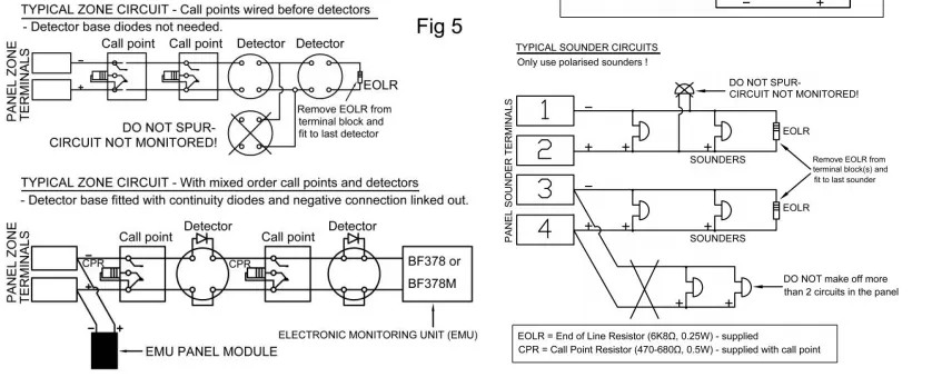
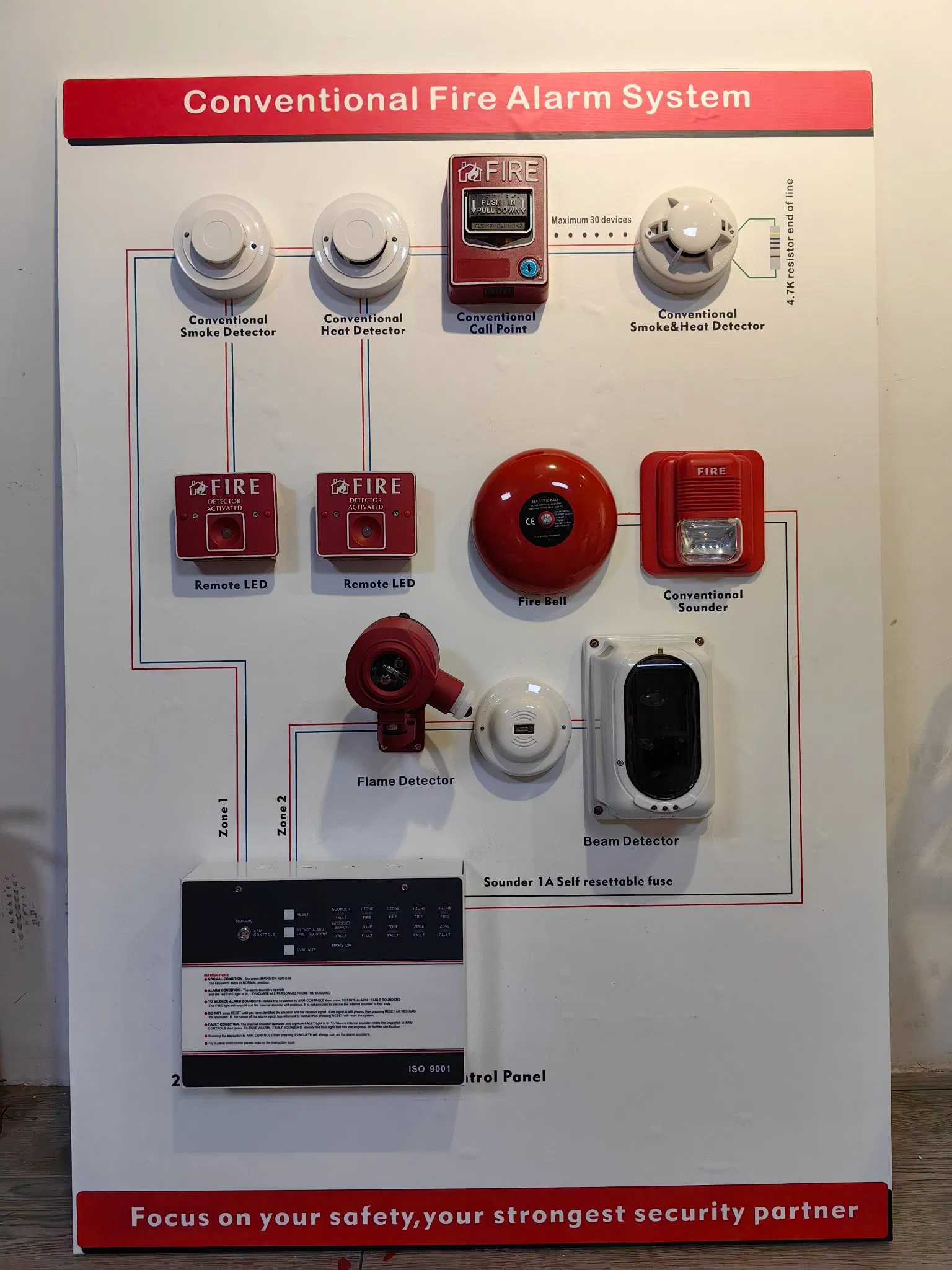
All cables must be installed in accordance with applicable national standards (e.g., BS 7671 and BS 5839-1). Fire resistant, screened cable should be used throughout. Mains wiring should be segregated from extra low voltage field wiring.

Mains Supply: Fixed wiring using 3 core cable (1mm² to 2.5mm²), fed from an isolating switched fused spur at 3A. The supply must be exclusive to the panel.

🔍 Testing Procedures
Panel Testing

When testing with the lid open, always isolate Mains and disconnect batteries. Ensure end-of-line resistors are fitted in sounder and detector terminal blocks if testing before full installation.
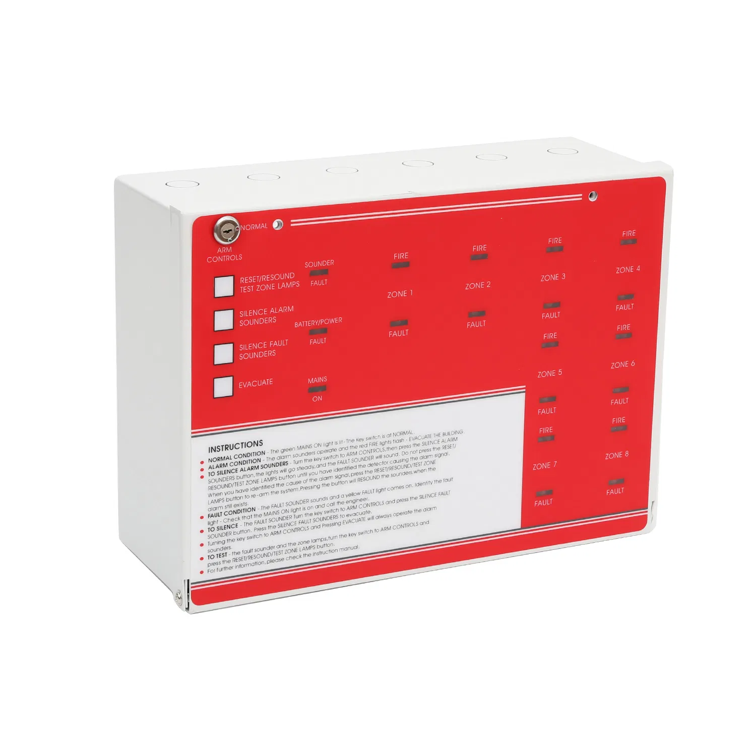
Power Supply Monitoring Circuit

Switch off the Mains. The BATTERY/POWER SUPPLY FAULT indicator should light and the beeper sound. Reconnect Mains; the panel should revert to normal. Disconnecting the battery should trigger similar fault indicators.
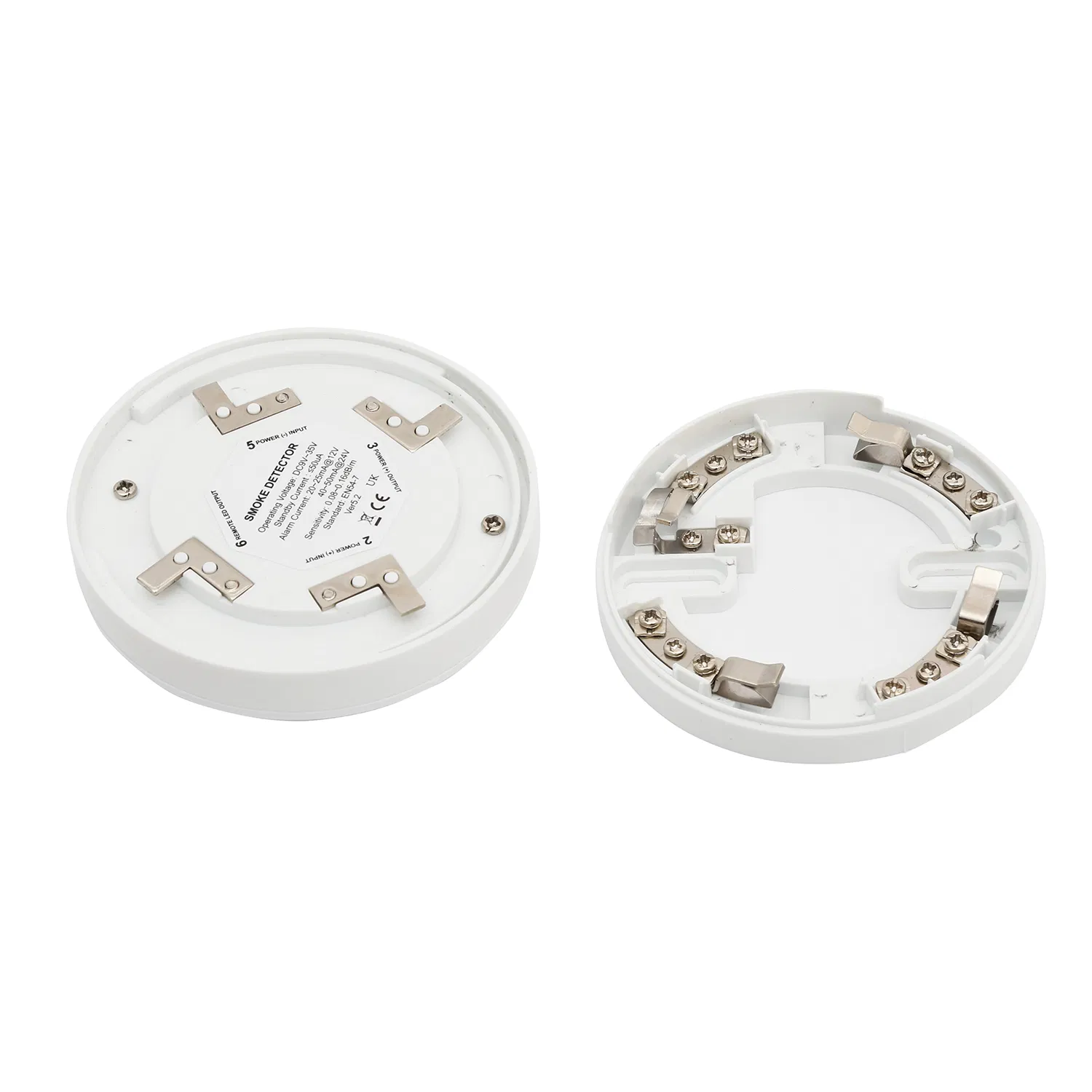
Sounder Monitoring Circuits

Short the sounder terminals 1&2. The SOUNDER FAULT indicator will light. Open circuit terminals 3&4 by disconnecting the end-of-line resistor; the fault indicator should also trigger.

Detector Monitoring Circuit

Four conditions can exist:

  • Normal Condition: Current flows via EOLD to monitor wiring.
  • Open Circuit Fault: Wiring is broken; adjust potentiometer (VR1) if needed to fix zone voltage.
  • Short Circuit Fault: Excessive current flow detected.
  • Fire Condition: Triggered by detectors or manual call points (470 to 680Ω resistors).
📊 Technical Specifications
Input VoltageAC 100-240V, 50/60HzCapacityHigh EMI Immunity
Internal Power SupplyDC 30V 3ABackup BatteryDC 12V/2.2AH * 2 (not included)
Total Output Current≤200mA @ 220VDimension325x265x100mm
Chipset32-bit Micro processorOperating Temp0ºC ~ +50ºC
Zones1-8 Zone(s)MaterialIron
🖼️ Product Gallery
Frequently Asked Questions
1. Who should install and maintain this fire alarm equipment? The equipment must only be installed and maintained by a suitably skilled and technically competent person to ensure safety and compliance.
2. What type of cables should be used for the installation? Fire resistant, screened cables must be used throughout the installation. Mains wiring must be kept separate from the extra low voltage field wiring.
3. Can I change panel connections while the power is on? No, you must never change any panel connections while the power (either mains or battery) is applied to the panel.
4. What are the common monitoring faults detected by the panel? The panel monitors for Open Circuit Faults (broken wiring), Short Circuit Faults (excessive current), and Power Supply/Battery Faults.
5. What is the maximum number of detectors supported per zone? Depending on the specific model and configuration, it typically supports between 20 to 30 detectors per zone.
6. Is the backup battery included in the package? No, the backup batteries (typically 2*12V) are not included and must be sourced separately.

Related Products